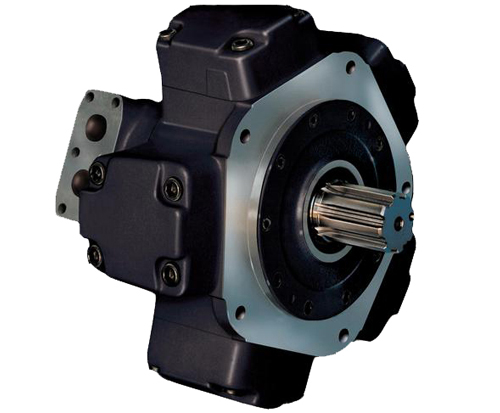
Fixed displacement radial piston motor
Maximum pressure up to 420 bar (6000 psi)
Torque up to 35000 Nm (25815 lbf.ft)
Temperature range -30 to +80 °C (-22° to +176°F)
MR motor: MR350 MR450 MR600 MR700 MR1100 MR1600 MR1800 MR2400 MR2800 MR3600 MR4500 MR6500 MR7000
MRE motor: MRE330 MRE500 MRE800 MRE1400 MRE2100 MRE3100 MRE5400 MRE8200
The outstanding performance of this motor is the result of an original and patented design.
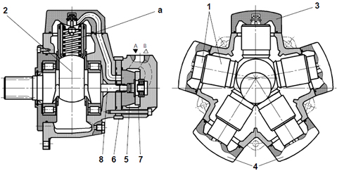
The principle is to transmit the effort from the stator to the rotating shaft (2) by means of a pressurized column of oil (a) instead of the more common connecting rods, pistons, pads and pins. This oil column is contained by a telescopic cylinder (1) with a mechanical connection at the lips at each end which seal against the spherical surfaces of the cylinder-heads (3) and the spherical surface of the rotating shaft (4). These lips retain their circular cross section when stressed by the pressure so there is no alteration in the sealing geometry. The particular selection of materials and optimization of design has minimized both the friction and the leakage. Another advantage of this design stems from the elimination of any connecting rods; the cylinder can only expand and retract linearly so there are no transverse components of the thrust. This means no oval wear on the moving parts and no side forces on the cylinder joints. A consequence of this novel design is a significant reduction in weight and overall size compared with other motors of the same capacity. The timing system is realized by means of a rotary valve (5) driven by the rotary valve driving shaft (8) that it is connected to the rotating shaft. The rotary valve rotates between the rotary valve plates (6) and the reaction ring (7) which is fixed with the motor"s housing. This timing system is also of a patented design being pressure balanced and self compensating for thermal expansion. The advantages of this type of valve coupled with a revolutionary cylinder arrangement produce a motor with extremely high values of mechanical and volumetric efficiency. The torque output is smooth even at very low speed and the motor gives a high performance starting under load.
Features and Benefits
• high power to weight ratio
• high volumetric and mechanical efficiency
• high resistance to thermal shock
• very low operating noise levels
• suitable for fire-resistant and biologically degradable fluids
• extremely well suited for control engineering applications
• reversible operation (motor and pump)
Technical Data
Table of values (theoretical values)
|
Size Motor version
|
Displacement
|
Moment inertia of rotating parts
|
Theoretical specific torque
|
Min. start. torque
/ Theoretical torque
|
Maximum Pressure
|
Speed range
|
Maximum output power
|
Weight
|
|
input
|
|
|
flushing
|
flushing
|
|
cont.
|
int.
|
peak
|
A+B *
|
Drain
|
without
|
with
|
without
|
with
|
|
V
|
J
|
|
%
|
p
|
p
|
p
|
p
|
p
|
n
|
n
|
P
|
P
|
m
|
|
in3
|
lb.in2
|
lb.ft/psi
|
|
psi
|
psi
|
psi
|
psi
|
psi
|
rpm
|
rpm
|
Hp
|
Hp
|
lb
|
|
M R E
|
MRE330
|
20.28
|
22.38
|
0.270
|
90
|
3046
|
3626
|
5076
|
5802
|
72.5 (218 psi with "F1" shaft seal)
|
1-750
|
1-750
|
42.9
|
65.7
|
110.2
|
|
MRE500
|
30.38
|
78.53
|
0.403
|
90
|
1-600
|
1-600
|
61.7
|
93.9
|
169.8
|
|
MRE800
|
49.08
|
122.47
|
0.651
|
90
|
1-450
|
1-450
|
87.2
|
124.7
|
213.8
|
|
MRE1400
|
83.6
|
154.28
|
1.109
|
92
|
0.5-280
|
0.5-280
|
103.3
|
136.8
|
319.7
|
|
MRE2100
|
127.6
|
291.86
|
1.693
|
91
|
0.5-250
|
0.5-250
|
134.1
|
198.5
|
487.2
|
|
MRE3100
|
189.4
|
1016.83
|
2.512
|
91
|
0.5-215
|
0.5-215
|
167.6
|
254.8
|
725.3
|
|
MRE5400
|
329.6
|
1713.72
|
4.374
|
92
|
0.5-120
|
0.5-160
|
187.7
|
281.6
|
1129
|
|
MRE8200
|
502
|
3887.52
|
6.657
|
92
|
0.5-90
|
0.5-120
|
228
|
335.3
|
1786
|
|
M R
|
MR33
|
1.96
|
1.48
|
0.025
|
90
|
3626
|
4351
|
6092
|
5802
|
72.5 (218 psi with
shaft seal)
|
1-1400
|
1-1400
|
8.9
|
13.4
|
66.14
|
|
MR57
|
3.44
|
1.59
|
0.046
|
90
|
1-1300
|
1-1300
|
14.8
|
22.8
|
66.14
|
|
MR73
|
4.43
|
4.79
|
0.061
|
90
|
1-1200
|
1-1200
|
20.2
|
26.8
|
83.78
|
|
MR93
|
5.65
|
5.16
|
0.076
|
90
|
1-1150
|
1-1150
|
22.8
|
33.5
|
83.78
|
|
MR110
|
6.65
|
5.53
|
0.087
|
90
|
1-1100
|
1-1100
|
24.1
|
37.6
|
83.78
|
|
MR125
|
7.61
|
19.44
|
0.102
|
90
|
1-900
|
1-900
|
22.8
|
33.5
|
101.4
|
|
MR160
|
9.75
|
19.65
|
0.129
|
90
|
1-900
|
1-900
|
26.8
|
40.2
|
101.4
|
|
MR190
|
11.69
|
19.89
|
0.155
|
90
|
1-850
|
1-850
|
32.2
|
48.3
|
101.4
|
|
MR200
|
12.16
|
19.56
|
0.163
|
90
|
1-800
|
1-800
|
33.5
|
51.0
|
110.2
|
|
MR250
|
15.31
|
20.78
|
0.203
|
90
|
1-800
|
1-800
|
42.9
|
64.4
|
110.2
|
|
MR300
|
18.56
|
22.36
|
0.244
|
90
|
1-750
|
1-750
|
46.9
|
71.1
|
110.2
|
|
MR350
|
21.33
|
77.19
|
0.283
|
90
|
1-640
|
1-640
|
55.0
|
83.1
|
169.8
|
|
MR450
|
27.56
|
78.53
|
0.366
|
90
|
1-600
|
1-600
|
61.7
|
100.6
|
169.8
|
|
MR450
|
27.56
|
78.53
|
0.366
|
90
|
|
|
|
|
|
1-600
|
1-600
|
61.7
|
100.6
|
169.8
|
|
MR600
|
37.10
|
90.58
|
0.493
|
90
|
|
|
|
|
|
1-520
|
1-520
|
75.1
|
112.6
|
213.8
|
|
MR700
|
43.09
|
122.47
|
0.575
|
90
|
|
|
|
|
|
1-500
|
1-500
|
87.2
|
130.1
|
213.8
|
|
MR1100
|
68.7
|
154.28
|
0.910
|
90
|
|
|
|
|
|
0.5-330
|
0.5-330
|
103.3
|
159.6
|
308.6
|
|
MR1600
|
97.5
|
227.73
|
1.292
|
90
|
|
|
|
|
|
0.5-260
|
0.5-260
|
128.7
|
193.1
|
460.8
|
|
MR1800
|
110.4
|
291.86
|
1.465
|
90
|
|
|
|
|
|
0.5-250
|
0.5-250
|
138.1
|
205.2
|
460.8
|
|
MR2400
|
139.9
|
968.89
|
1.937
|
90
|
|
|
|
|
|
0.5-220
|
0.5-220
|
160.9
|
245.4
|
716.5
|
|
MR2800
|
170.4
|
1016.83
|
2.263
|
90
|
|
|
|
|
|
0.5-215
|
0.5-215
|
170.3
|
260.2
|
716.5
|
|
MR3600
|
221.9
|
1657.78
|
2.944
|
90
|
|
|
|
|
|
0.5-150
|
0.5-180
|
164.9
|
248.1
|
1120
|
|
MR4500
|
274.8
|
1713.72
|
3.346
|
91
|
|
|
|
|
|
0.5-130
|
0.5-170
|
187.7
|
281.6
|
1120
|
|
MR6500
|
394.2
|
3887.52
|
5.267
|
91
|
|
|
|
|
|
0.5-110
|
0.5-130
|
221.3
|
321.8
|
1764
|
|
MR7000
|
408.7
|
3887.52
|
5.665
|
91
|
|
|
|
|
|
0.5-100
|
0.5-130
|
228
|
335.3
|
1764
|
At a certain ambient temperature, the operating temperature in the circuit is 122°F (50°C). In the optimum operating viscosity range, this corresponds to viscosity grades VG 46 or VG 68; VG 68 should be selected. IMPORTANT: The drain oil temperature is influenced by pressure and speed and is usually higher than the circuit temperature or the tank temperature. At no point in the system, however, may the temperature be higher than 176°F (80°C).
If the optimum conditions cannot be met due to the extreme operating parameters or high ambient temperature, we always recommend flushing the motor case in order to operate within the viscosity limits.
OPERATING VISCOSITY RANGE
The viscosity, quality and cleanliness of operating fluids are decisive factors in determining the reliability, performance and life-time of an hydraulic component. The maximum life-time and performance are achieved within the recommended viscosity range. For applications that go beyond this range, this viscosity refers to the temperature of the fluid entering the motor, and at the same time to the temperature inside the motor housing (case temperature). We recommend selecting the viscosity of the fluid based on the maximum operating temperature, to remain within the recommended viscosity range. To reach the value of maximum continuous power the operating viscosity should be within the recommended viscosity range of 30 - 50 CST.
CHOOSING THE TYPE OF FLUID ACCORDING TO THE OPERATING TEMPERATURE
The operating temperature of the motor is defined as the greater temperature between that of the incoming fluid and that of the fluid inside the motor housing (case temperature).We recommend that you choose the viscosity of the fluid based on the maximum operating temperature, to remain within the recommended viscosity range. We recommend that the higher viscosity grade must be selected in each case. The motor life also depends on the fluid filtration.
Motor START-UP
The motor does not require any special running in, but all residual impurities in the system must be eliminated by running the motor at low speed and with no applied load, granting the minimum necessary inlet pressure.
After a brief period in service, the system filters should be cleaned. This operation will also lead to the air venting from motor cylinders; air inside the motor cylinders may increase the possible noise at the start-up of the motor.
Make sure the motor case has been filled.